Projekt:Gartenwassersteuerung: Unterschied zwischen den Versionen
Pagaty (Diskussion | Beiträge) Keine Bearbeitungszusammenfassung |
Pagaty (Diskussion | Beiträge) Keine Bearbeitungszusammenfassung |
||
| (8 dazwischenliegende Versionen desselben Benutzers werden nicht angezeigt) | |||
| Zeile 11: | Zeile 11: | ||
==Motivation== | ==Motivation== | ||
Für meinen Garten möchte ich wahlweise das Wasser aus der Zisterne, und bei zu niedrigem Stand aus der Hausleitung haben. | |||
Desweiteren möchte ich meine Verbraucher separat ansteuern können. | |||
Dazu benötige ich 8 Relais die ich mit Home Assistant und ESPHome steuern möchte. | |||
==Vorbereitung der Relais== | |||
Es gibt tolle 4er Relais mit direkt verbautem ESP-8266-1. | |||
Da ich acht Relais benötige nehme ich zwei davon. | |||
([https://www.google.com/imgres?imgurl=https://ae01.alicdn.com/kf/HTB139uoazDuK1RjSszdq6xGLpXaM.jpg&imgrefurl=https://de.aliexpress.com/i/32967159754.html&docid=TLFzrkUPBT9-LM&tbnid=ew6in-Owg_e41M:&vet=1&w=1000&h=1000&source=sh/x/im Dort zu sehen]) | |||
Die Kugelventile sind dreiadrig, sodaß sie je nachdem welche Ader Strom bekommt offen oder zu sind. (Sie nehmen in Endposition keine Leistung mehr auf) | |||
Meine technischen Mentoren M. und N. sind dann gleich auf die Idee gekommen, das fertig Bauteile ohne Modifizierung nicht einbaufähig sind (wäre ja langweilig) | |||
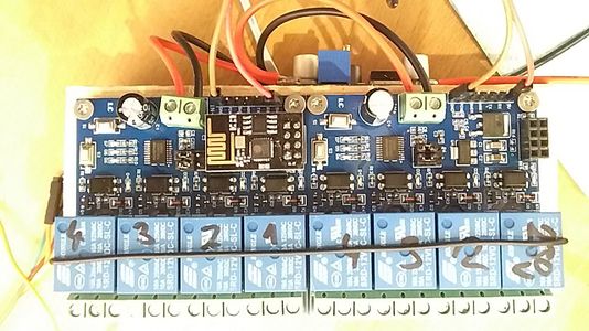
Zwei ESPs nebeneinander sind ja unnötig. Allerdings ist der ESP-8266-1 sehr beschränkt was die Anzahl der Pins betrifft. Glücklicherweise ist das Board sinnvoll ausgebaut, und nutzt nur einen Pin und übergibt ein rx tx Signal an einen zweiten Microcontroller auf dem Board. | |||
Also schnell mal den zweiten Controller an den zweiten pin des ESP gehängt. (N. hat das ganze dann Softwaremäßig kompensiert) | |||
<gallery heights=200px mode="packed" > | |||
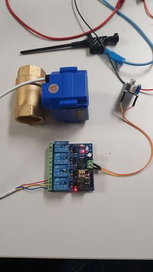
Image:verlötet.jpg|Fertig gelötetes Relaisboard | |||
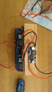
Image:stromversorgung.jpg|Stromversorgung auf 12V runterziehen | |||
Image:kompl.jpg|Fertiges Bauteil mit Verkabelung rx-tx | |||
</gallery> | |||
Die Ventile werden mit 12V betrieben die nach diesem Umbau vom Board geliefert werden. | |||
Um meine sieben Ventile mit nur einem Relais zu bedienen musste dann noch das Relais so verkabelt werden, dass entweder NO oder NC je nach Schaltzustand Strom haben.
| |||
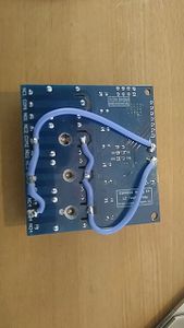
M. hat dann erst mal den Kontakt desCOM Eingang mittels einer Bohrmaschine getrennt. (genialer Einfall) | |||
Danach wurde hinter der Unterbrechung die Masse des Boards an die COM Leitung gelegt. | |||
Vor der Unterbrechung (Bohrung Bild) wurde die Spannung vom Board an COM gelegt. | |||
Dadurch schaltet das Relais jetzt 12v entweder auf NC oder NO. | |||
Danke M. | |||
==Progamm== | |||
Die Programmierarbeit mit ESP Home ist normalerweise leichter als ein Kinderspiel. | |||
als BSP so in etwa: | |||
<code> | |||
sensor: | |||
- platform: ultrasonic | |||
unit_of_measurement: "%" | |||
icon: "mdi:water-percent" | |||
trigger_pin: D2 | |||
echo_pin: D1 | |||
update_interval: 5s | |||
name: "Ultrasonic Sensor" | |||
</code> | |||
(mehr ist es nicht - wirklich) | |||
In diesem Fall leider nicht ganz.
Da die Relais über UART angesprochen werden, muss dem ESP noch gesagt werden, welchen der beiden Pins er jetzt verwenden soll. | |||
Das hat N. grandioses geleistet: | |||
<code> | |||
uart: | |||
- id: uart1 | |||
baud_rate: 115200 # speed to STC15L101EW | |||
tx_pin: GPIO1 | |||
- baud_rate: 115200 # speed to STC15L101EW | |||
id: uart2 | |||
tx_pin: GPIO2 | |||
switch: | |||
- platform: template | |||
name: "Zisternen Pumpe" | |||
id: "R1" | |||
turn_on_action: | |||
- switch.turn_on: uart_r1_on | |||
turn_off_action: | |||
- switch.turn_on: uart_r1_off | |||
optimistic: true | |||
- platform: uart | |||
id: uart_r1_on | |||
internal: true | |||
uart_id: uart1 | |||
data: [0xA0, 0x01, 0x01, 0xA2] | |||
- platform: uart | |||
id: uart_r1_off | |||
internal: true | |||
uart_id: uart1 | |||
data: [0xA0, 0x01, 0x00, 0xA1] | |||
- platform: template | |||
name: "Wasserhahn Zisterne" | |||
id: "R2" | |||
turn_on_action: | |||
- switch.turn_on: uart_r2_on | |||
turn_off_action: | |||
- switch.turn_on: uart_r2_off | |||
optimistic: true | |||
- platform: uart | |||
id: uart_r2_on | |||
internal: true | |||
uart_id: uart1 | |||
data: [0xA0, 0x02, 0x01, 0xA3] | |||
- platform: uart | |||
id: uart_r2_off | |||
internal: true | |||
uart_id: uart1 | |||
data: [0xA0, 0x02, 0x00, 0xA2] | |||
- platform: template | |||
name: "Wasserhahn Mitte" | |||
id: "R3" | |||
turn_on_action: | |||
- switch.turn_on: uart_r3_on | |||
turn_off_action: | |||
- switch.turn_on: uart_r3_off | |||
optimistic: true | |||
- platform: uart | |||
id: uart_r3_on | |||
internal: true | |||
uart_id: uart1 | |||
data: [0xA0, 0x03, 0x01, 0xA4] | |||
- platform: uart | |||
id: uart_r3_off | |||
internal: true | |||
uart_id: uart1 | |||
data: [0xA0, 0x03, 0x00, 0xA3] | |||
- platform: template | |||
name: "R4" | |||
id: "R4" | |||
turn_on_action: | |||
- switch.turn_on: uart_r4_on | |||
turn_off_action: | |||
- switch.turn_on: uart_r4_off | |||
optimistic: true | |||
- platform: uart | |||
id: uart_r4_on | |||
internal: true | |||
uart_id: uart1 | |||
data: [0xA0, 0x04, 0x01, 0xA5] | |||
- platform: uart | |||
id: uart_r4_off | |||
internal: true | |||
uart_id: uart1 | |||
data: [0xA0, 0x04, 0x00, 0xA4] | |||
- platform: template | |||
name: "R5" | |||
id: "R5" | |||
turn_on_action: | |||
- switch.turn_on: uart_r5_on | |||
turn_off_action: | |||
- switch.turn_on: uart_r5_off | |||
optimistic: true | |||
- platform: uart | |||
id: uart_r5_on | |||
internal: true | |||
uart_id: uart2 | |||
data: [0xA0, 0x01, 0x01, 0xA2] | |||
- platform: uart | |||
id: uart_r5_off | |||
internal: true | |||
uart_id: uart2 | |||
data: [0xA0, 0x01, 0x00, 0xA1] | |||
- platform: template | |||
name: "R6" | |||
id: "R6" | |||
turn_on_action: | |||
- switch.turn_on: uart_r6_on | |||
turn_off_action: | |||
- switch.turn_on: uart_r6_off | |||
optimistic: true | |||
- platform: uart | |||
id: uart_r6_on | |||
internal: true | |||
uart_id: uart2 | |||
data: [0xA0, 0x02, 0x01, 0xA3] | |||
- platform: uart | |||
id: uart_r6_off | |||
internal: true | |||
uart_id: uart2 | |||
data: [0xA0, 0x02, 0x00, 0xA2] | |||
- platform: template | |||
name: "R7" | |||
id: "R7" | |||
turn_on_action: | |||
- switch.turn_on: uart_r7_on | |||
turn_off_action: | |||
- switch.turn_on: uart_r7_off | |||
optimistic: true | |||
- platform: uart | |||
id: uart_r7_on | |||
internal: true | |||
uart_id: uart2 | |||
data: [0xA0, 0x03, 0x01, 0xA4] | |||
- platform: uart | |||
id: uart_r7_off | |||
internal: true | |||
uart_id: uart2 | |||
data: [0xA0, 0x03, 0x00, 0xA3] | |||
- platform: template | |||
name: "R8" | |||
id: "R8" | |||
turn_on_action: | |||
- switch.turn_on: uart_r8_on | |||
turn_off_action: | |||
- switch.turn_on: uart_r8_off | |||
optimistic: true | |||
- platform: uart | |||
id: uart_r8_on | |||
internal: true | |||
uart_id: uart2 | |||
data: [0xA0, 0x04, 0x01, 0xA5] | |||
- platform: uart | |||
id: uart_r8_off | |||
internal: true | |||
uart_id: uart2 | |||
data: [0xA0, 0x04, 0x00, 0xA4] | |||
</code> | |||
So können jetzt alle Relais mit nur einem ESP angesprochen werden. | |||
==Endmontage== | |||
Jetzt muss nur noch die Masse vom Kugelventil in den COM geschraubt und die beiden Phasen in NO un NC geschraubt werden. | |||
Dann fängt die fricklei mit Home Assistant Automationen an. | |||
Aktuelle Version vom 10. Juni 2020, 19:28 Uhr
| Gartenwassersteuerung
Status: stable | |
|---|---|

| |
| Beschreibung | Für Gartenbewässerung el. Kugelventile mit ESP-Relais steuern |
| Ansprechpartner | Pagaty |
| Version | 1.0 |
Motivation
Für meinen Garten möchte ich wahlweise das Wasser aus der Zisterne, und bei zu niedrigem Stand aus der Hausleitung haben. Desweiteren möchte ich meine Verbraucher separat ansteuern können.
Dazu benötige ich 8 Relais die ich mit Home Assistant und ESPHome steuern möchte.
Vorbereitung der Relais
Es gibt tolle 4er Relais mit direkt verbautem ESP-8266-1. Da ich acht Relais benötige nehme ich zwei davon.
Die Kugelventile sind dreiadrig, sodaß sie je nachdem welche Ader Strom bekommt offen oder zu sind. (Sie nehmen in Endposition keine Leistung mehr auf)
Meine technischen Mentoren M. und N. sind dann gleich auf die Idee gekommen, das fertig Bauteile ohne Modifizierung nicht einbaufähig sind (wäre ja langweilig)
Zwei ESPs nebeneinander sind ja unnötig. Allerdings ist der ESP-8266-1 sehr beschränkt was die Anzahl der Pins betrifft. Glücklicherweise ist das Board sinnvoll ausgebaut, und nutzt nur einen Pin und übergibt ein rx tx Signal an einen zweiten Microcontroller auf dem Board. Also schnell mal den zweiten Controller an den zweiten pin des ESP gehängt. (N. hat das ganze dann Softwaremäßig kompensiert)
Die Ventile werden mit 12V betrieben die nach diesem Umbau vom Board geliefert werden.
Um meine sieben Ventile mit nur einem Relais zu bedienen musste dann noch das Relais so verkabelt werden, dass entweder NO oder NC je nach Schaltzustand Strom haben.
M. hat dann erst mal den Kontakt desCOM Eingang mittels einer Bohrmaschine getrennt. (genialer Einfall) Danach wurde hinter der Unterbrechung die Masse des Boards an die COM Leitung gelegt. Vor der Unterbrechung (Bohrung Bild) wurde die Spannung vom Board an COM gelegt.
Dadurch schaltet das Relais jetzt 12v entweder auf NC oder NO.
Danke M.
Progamm
Die Programmierarbeit mit ESP Home ist normalerweise leichter als ein Kinderspiel.
als BSP so in etwa:
sensor:
 - platform: ultrasonic
   unit_of_measurement: "%"
   icon: "mdi:water-percent"
   trigger_pin: D2
   echo_pin: D1
   update_interval: 5s
   name: "Ultrasonic Sensor"
(mehr ist es nicht - wirklich)
In diesem Fall leider nicht ganz. Da die Relais über UART angesprochen werden, muss dem ESP noch gesagt werden, welchen der beiden Pins er jetzt verwenden soll.
Das hat N. grandioses geleistet:
uart:
 - id: uart1
   baud_rate: 115200 # speed to STC15L101EW
   tx_pin: GPIO1
 - baud_rate: 115200 # speed to STC15L101EW
   id: uart2
   tx_pin: GPIO2
switch:
 - platform: template
   name: "Zisternen Pumpe"
   id: "R1"
   turn_on_action:
     - switch.turn_on: uart_r1_on
   turn_off_action:
     - switch.turn_on: uart_r1_off
   optimistic: true
 - platform: uart
   id: uart_r1_on
   internal: true
   uart_id: uart1
   data: [0xA0, 0x01, 0x01, 0xA2]
 - platform: uart
   id: uart_r1_off
   internal: true
   uart_id: uart1
   data: [0xA0, 0x01, 0x00, 0xA1]
 - platform: template
   name: "Wasserhahn Zisterne"
   id: "R2"
   turn_on_action:
     - switch.turn_on: uart_r2_on
   turn_off_action:
     - switch.turn_on: uart_r2_off
   optimistic: true
 - platform: uart
   id: uart_r2_on
   internal: true
   uart_id: uart1
   data: [0xA0, 0x02, 0x01, 0xA3]
 - platform: uart
   id: uart_r2_off
   internal: true
   uart_id: uart1
   data: [0xA0, 0x02, 0x00, 0xA2]
 - platform: template
   name: "Wasserhahn Mitte"
   id: "R3"
   turn_on_action:
     - switch.turn_on: uart_r3_on
   turn_off_action:
     - switch.turn_on: uart_r3_off
   optimistic: true
 - platform: uart
   id: uart_r3_on
   internal: true
   uart_id: uart1
   data: [0xA0, 0x03, 0x01, 0xA4]
 - platform: uart
   id: uart_r3_off
   internal: true
   uart_id: uart1
   data: [0xA0, 0x03, 0x00, 0xA3]
 - platform: template
   name: "R4"
   id: "R4"
   turn_on_action:
     - switch.turn_on: uart_r4_on
   turn_off_action:
     - switch.turn_on: uart_r4_off
   optimistic: true
 - platform: uart
   id: uart_r4_on
   internal: true
   uart_id: uart1
   data: [0xA0, 0x04, 0x01, 0xA5]
 - platform: uart
   id: uart_r4_off
   internal: true
   uart_id: uart1
   data: [0xA0, 0x04, 0x00, 0xA4]

 - platform: template
   name: "R5"
   id: "R5"
   turn_on_action:
     - switch.turn_on: uart_r5_on
   turn_off_action:
     - switch.turn_on: uart_r5_off
   optimistic: true
 - platform: uart
   id: uart_r5_on
   internal: true
   uart_id: uart2
   data: [0xA0, 0x01, 0x01, 0xA2]
 - platform: uart
   id: uart_r5_off
   internal: true
   uart_id: uart2
   data: [0xA0, 0x01, 0x00, 0xA1]
 - platform: template
   name: "R6"
   id: "R6"
   turn_on_action:
     - switch.turn_on: uart_r6_on
   turn_off_action:
     - switch.turn_on: uart_r6_off
   optimistic: true
 - platform: uart
   id: uart_r6_on
   internal: true
   uart_id: uart2
   data: [0xA0, 0x02, 0x01, 0xA3]
 - platform: uart
   id: uart_r6_off
   internal: true
   uart_id: uart2
   data: [0xA0, 0x02, 0x00, 0xA2]
 - platform: template
   name: "R7"
   id: "R7"
   turn_on_action:
     - switch.turn_on: uart_r7_on
   turn_off_action:
     - switch.turn_on: uart_r7_off
   optimistic: true
 - platform: uart
   id: uart_r7_on
   internal: true
   uart_id: uart2
   data: [0xA0, 0x03, 0x01, 0xA4]
 - platform: uart
   id: uart_r7_off
   internal: true
   uart_id: uart2
   data: [0xA0, 0x03, 0x00, 0xA3]
 - platform: template
   name: "R8"
   id: "R8"
   turn_on_action:
     - switch.turn_on: uart_r8_on
   turn_off_action:
     - switch.turn_on: uart_r8_off
   optimistic: true
 - platform: uart
   id: uart_r8_on
   internal: true
   uart_id: uart2
   data: [0xA0, 0x04, 0x01, 0xA5]
 - platform: uart
   id: uart_r8_off
   internal: true
   uart_id: uart2
   data: [0xA0, 0x04, 0x00, 0xA4]
So können jetzt alle Relais mit nur einem ESP angesprochen werden.
Endmontage
Jetzt muss nur noch die Masse vom Kugelventil in den COM geschraubt und die beiden Phasen in NO un NC geschraubt werden. Dann fängt die fricklei mit Home Assistant Automationen an.


